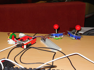
In a later post, you'll read about a parallelized version of pong painted on a grid of computer screens. This sub-project was to interface joysticks up to a controlling node in the pong cluster and give it a classic cabinet feel. The only difference is that it is displaying on 15 screens! Until we got this working, we had to watch an AI enjoy the game.
Hacking joysticks together with the Raspberry Pi is pretty straightforward once you learn some basic properties of GPIO (General Purpose Input/Output) Pins on the Raspberry Pi. Since we used joysticks where each switch only had two terminals, opposed to three or four, we couldn't design a circuit where the GPIO pins were either grounded or sourced at all times. This means that either pin would be in an undecided state, unless assigned otherwise via software. To remedy this, we assigned the pull_up_down flag to a down state. This tells the Raspberry Pi to always ground the pin until a noticeable current flows through it. The end code was written in python, using the RPi.GPIO library, and can be seen below:
This code was simply used to interface with the controllers. Once we received the desired behavior, we simply ported the code into the Pong game as a separate input thread. The RPi.GPIO library can be found on Google Code. There's a short set of instructions on how to install RPi.GPIO library on the Adafruit site.
Hacking joysticks together with the Raspberry Pi is pretty straightforward once you learn some basic properties of GPIO (General Purpose Input/Output) Pins on the Raspberry Pi. Since we used joysticks where each switch only had two terminals, opposed to three or four, we couldn't design a circuit where the GPIO pins were either grounded or sourced at all times. This means that either pin would be in an undecided state, unless assigned otherwise via software. To remedy this, we assigned the pull_up_down flag to a down state. This tells the Raspberry Pi to always ground the pin until a noticeable current flows through it. The end code was written in python, using the RPi.GPIO library, and can be seen below:
import RPi.GPIO as GPIO
import time

GPIO.setwarnings(False)
GPIO.setmode(GPIO.BOARD)

# Note that the pin assignments in
# the code differ from the ones on the RP
# 7=4, 11=17, 13=27, 15=22

up0 = 7
down0 = 11
up1 = 13
down1 = 15

GPIO.setup(up0, GPIO.IN, pull_up_down=GPIO.PUD_DOWN)
GPIO.setup(down0, GPIO.IN, pull_up_down=GPIO.PUD_DOWN)
GPIO.setup(up1, GPIO.IN, pull_up_down=GPIO.PUD_DOWN)
GPIO.setup(down1, GPIO.IN, pull_up_down=GPIO.PUD_DOWN)

while 1:
    #Print out commands
    if GPIO.input(up0):
        print "up0"
    elif GPIO.input(down0):
        print "down0"
    if GPIO.input(up1):
        print "up1"
    elif GPIO.input(down1):
        print "down1"
This code was simply used to interface with the controllers. Once we received the desired behavior, we simply ported the code into the Pong game as a separate input thread. The RPi.GPIO library can be found on Google Code. There's a short set of instructions on how to install RPi.GPIO library on the Adafruit site.
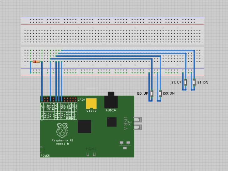
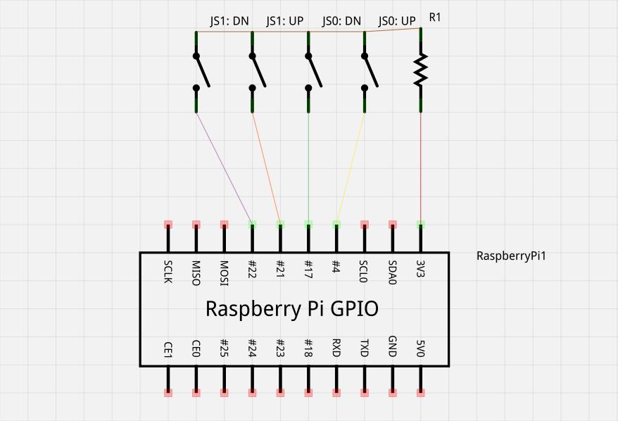
Writing the code gave us a pretty clear idea of the wiring setup:


- We have two terminal switch-board joysticks
- One switch per direction = Two switches per joystick = 8 wires
- Each switch would have current from the 3.3V GPIO pin running through a 22.3 Ohm resistor on one end separated from a wire connecting to a GPIO pin assigned to a paddle movement (ie. player one down).
- Closing the switch would complete the circuit making the forced down GPIO pin go up.

No comments:
Post a Comment